Ethernet

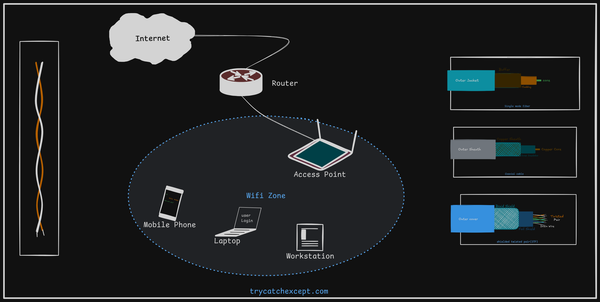
Ethernet is the world’s most widely used LAN technology, implemented in nearly 80% of LANs. It uses a bus topology and was developed at Xerox’s Palo Alto Research Center in the early 1970s.
Intel, Digital and Xerox cooperated to devise a production standard, which is informally called DIX Ethernet. IEEE now controls Ethernet standards. In its original version, an Ethernet LAN consisted of a single coaxial cable (also called as segment), called the ether, to which multiple computers connect. A standard requires a minimum separation of 3 meters between each pair of connections.
Ethernet Addressing Structure
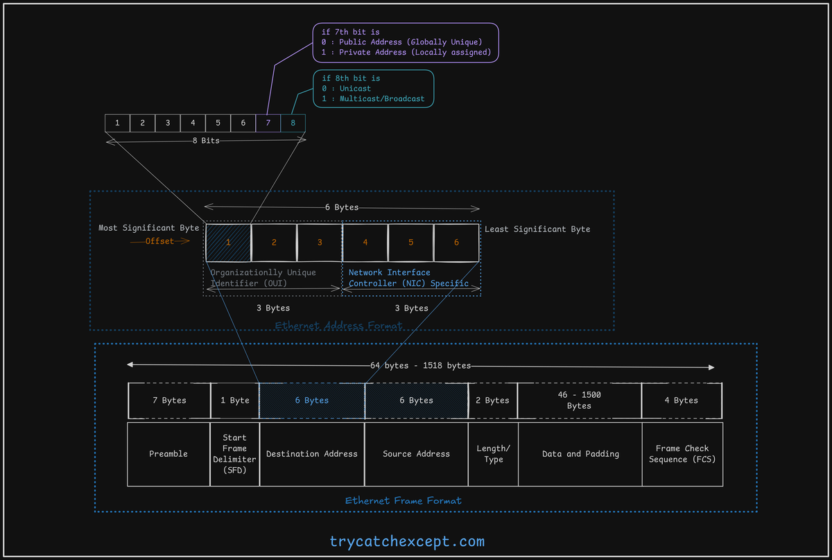
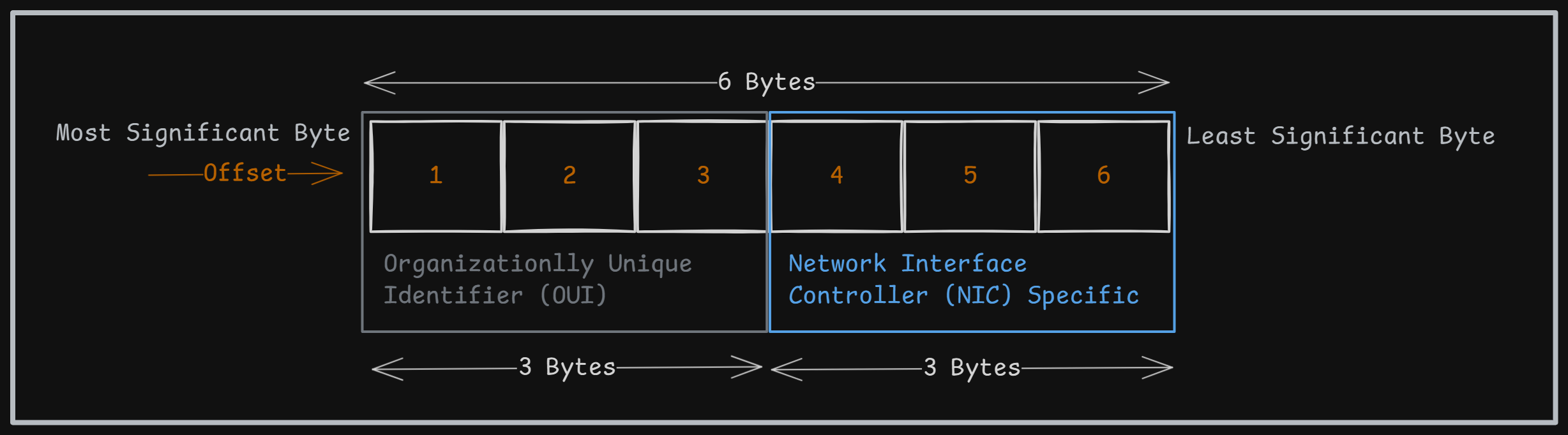
An Ethernet address is 6 bytes long, where the first 3 most significant bytes are assigned by IEEE, and the remaining 3 bytes are designated by the vendor.
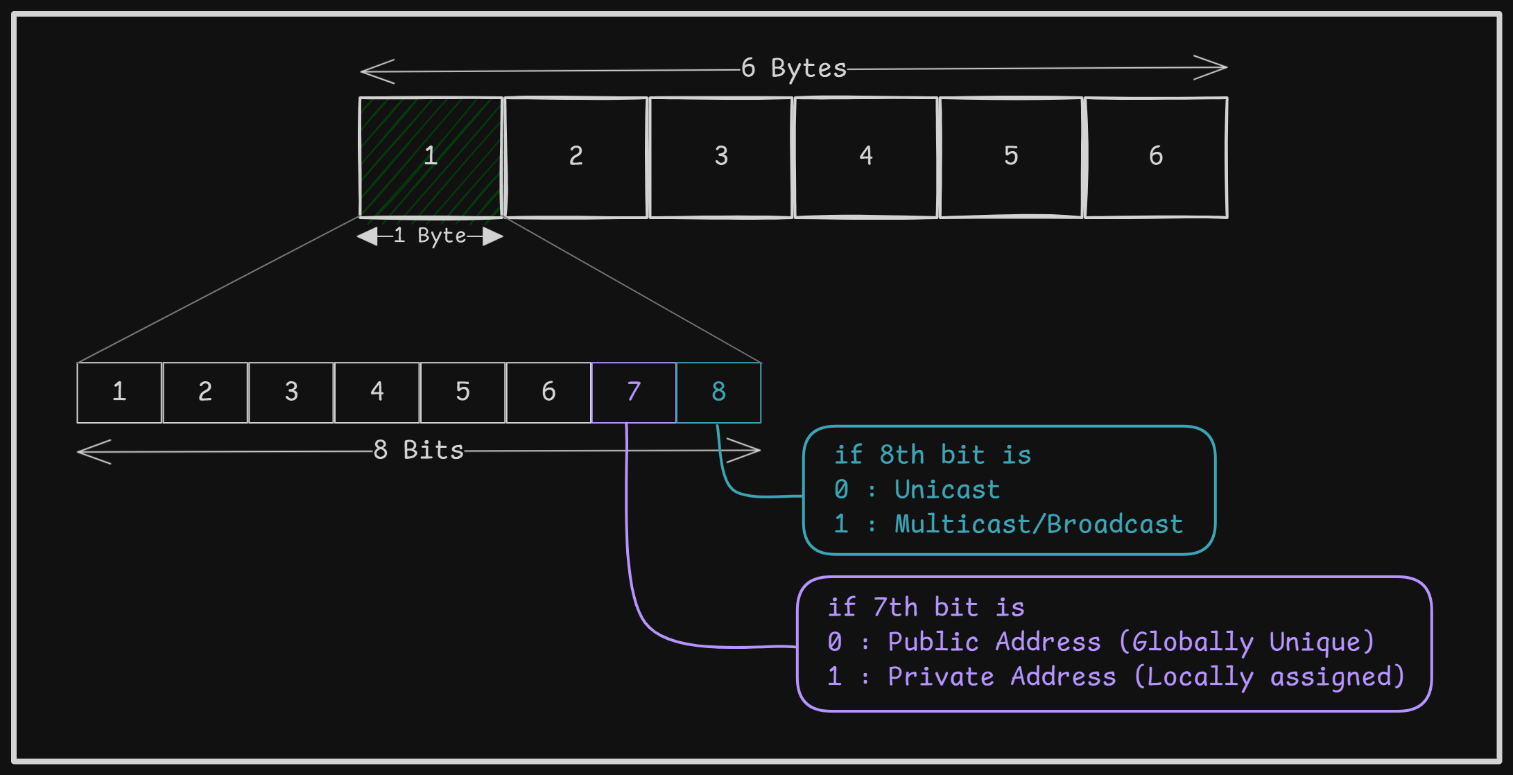
In Ethernet addressing, the 8th bit of the most significant byte determines whether the address functions as Unicast or Multicast/Broadcast. Likewise, the 7th bit of the most significant byte specifies if the address is private or public.
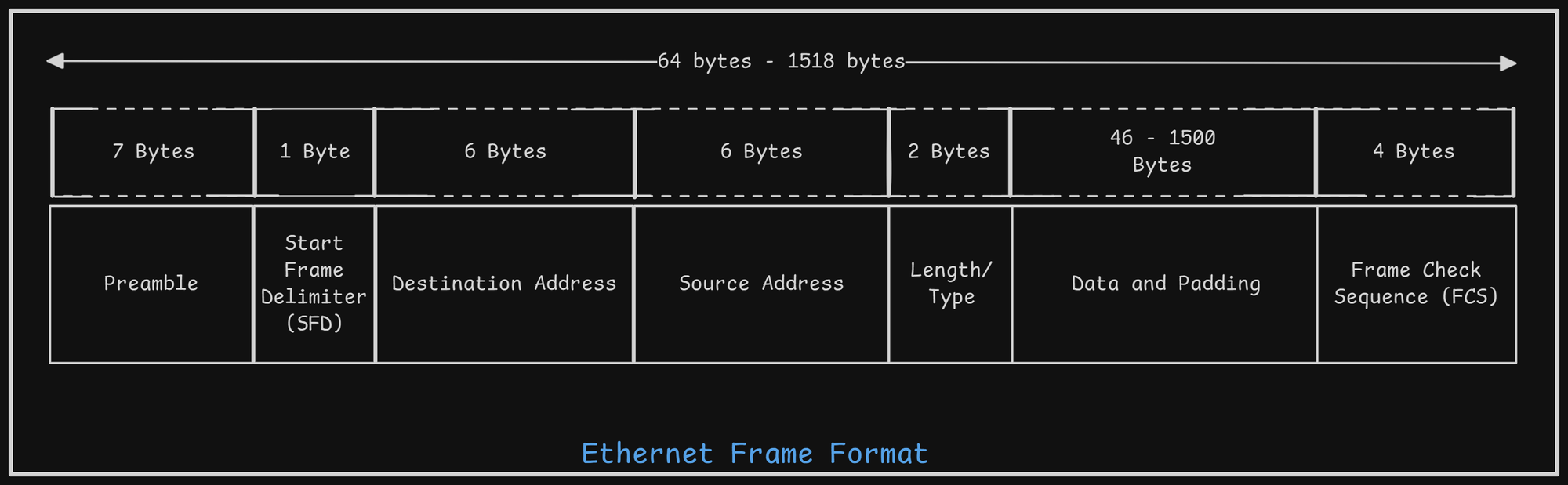
Ethernet Frame Format
-
Preamble (7 Bytes):
- Think of this as a "wake-up call."
- Consists of a repeating pattern (10101010) used by devices to synchronize their timing before the actual data arrives.
-
Start of Frame Delimiter (SFD) (1 Byte):
- Signals "Here comes the important stuff!"
- A specific pattern (10101011) that marks the end of the preamble and the beginning of the frame's core information, starting with the destination address.
-
Destination Address (DA) (6 Bytes):
- Specifies "Where is this going?"
- Identifies the intended recipient(s).
- The first bit indicates if it's for a single device (Unicast: 0) or a group (Multicast: 1).
- The second bit tells if the address is globally unique (0) or locally assigned (1). (The older 2-octet version is no longer used).
-
Source Address (SA) (6 Bytes):
- Specifies "Who sent this?"
- Identifies the originating device.
- Uses the same format as the DA, but the first bit is always 0 (Unicast) since a frame comes from only one source.
-
Length Field (2 Bytes):
- Answers "How much data is inside?"
- Indicates the number of bytes contained in the Data field (maximum 1500). This helps the receiver know where the data ends and the error check begins.
-
Data Field (46 - 1500 Bytes):
- This is the actual payload – the user data you're sending (often encapsulated within an LLC frame).
- Padding: If the data is less than 46 bytes, extra "padding" bytes are added to reach this minimum size.
- This minimum length is crucial for the network's collision detection mechanism to work correctly.
-
Frame Check Sequence (FCS) (4 Bytes):
- Acts as an "error detector."
- Contains a value calculated using a Cyclic Redundancy Check (CRC) on the frame's contents (from DA to Data field).
- The receiving device performs the same calculation. If the results don't match, it means the frame got corrupted during transmission, and the receiver discards it. If it matches, the data is considered error-free and passed on.
DIX Ethernet (Ethernet II) Frame Format:
Also known as the Ethernet II frame format. Key Difference from IEEE 802.3: Features a Type field instead of a Length field. The Type field identifies the protocol of the encapsulated data (e.g., IP, ARP, RARP).
CSMA/CD Protocol (Carrier Sense Multiple Access with Collision Detection)
-
Purpose: An access method used in shared-media Ethernet (a broadcast technology).
-
Core Idea: "Listen Before Transmit" combined with detecting collisions during transmission.
-
Key Functions:
- Transmitting and receiving data packets.
- Decoding packets, checking addresses validity before passing data up the protocol stack.
- Detecting errors within packets or on the network.
-
How it Works:
- Carrier Sense (Listen): Before sending, a device checks if the network media is busy or free.
- Media Busy: If the network is busy, the device waits a random amount of time before trying again.
- Media Free: If the network is free, the device starts transmitting its data frame.
- Collision Detection (Listen While Transmitting): Crucially, the device continues to listen to the network while it is transmitting. This is to detect if another device started transmitting simultaneously, causing a collision.
- Detecting Collisions: Collisions are typically detected when the signal amplitude on the network increases beyond the level of a single transmission.
- Minimum Frame Size Importance: Frames must be long enough to ensure the sending device is still transmitting when a signal from the farthest part of the network (potentially indicating a collision) arrives back. If frames were too short, a device might finish sending and stop listening before detecting a collision that occurred.
-
Collision Handling:
- Jam Signal: When a collision is detected, the transmitting devices briefly continue transmitting (a "jam signal") to ensure all devices on the network recognize the collision state.
- Stop Transmission: All transmitting devices involved in the collision stop sending their frames.
- Back-off Algorithm: Each device that experienced the collision calculates and waits for a random period of time. The randomness is key to preventing them from colliding again immediately.
- Retry: After its random back-off timer expires, a device can attempt to transmit again (starting back at Step 1).
- No Priority: Devices involved in a collision do not get priority over other devices when attempting to retransmit.
-
Post-Transmission:
- After successfully transmitting a complete frame without collision, the device returns to listening mode.
Ethernet Operation
Ethernet is a way for computers to communicate over a shared cable. Here’s how it works:
-
Listening Before Speaking:
Before a device sends data, it "listens" to the cable to check if it's free.- If the cable is quiet, it sends the data.
- If two devices send data at the same time, a collision happens.
-
Handling Collisions (CSMA/CD - Carrier Sense Multiple Access with Collision Detection):
When a collision happens:- Devices detect the collision.
- They immediately send a jam signal (32 bits) to inform all devices about the collision.
- Each device waits for a random amount of time before trying again. This prevents continuous collisions.
-
Random Waiting Time (Binary Exponential Backoff):
- After each collision, devices calculate a random wait time.
- The waiting time increases with the number of collisions (exponentially).
- After too many attempts (16), the device gives up and reports a failure.
-
Slot Time:
- Ethernet sets a "slot time," which is the time needed for a signal to travel to the farthest point and back.
- For example:
- 10/100 Mbps Ethernet: 512 bit-times (64 bytes).
- 1000 Mbps Ethernet: 4096 bit-times (512 bytes).
- Devices must detect collisions within this time.
-
Half-Duplex vs Full-Duplex:
- Half-Duplex: Devices can either send or receive at a time; collisions can occur.
- Full-Duplex: Devices send and receive at the same time; no collisions happen.
-
Frame Structure:
After starting transmission:- Devices send a preamble (for timing sync).
- Then send MAC addresses, headers, actual data, and a checksum (FCS) to detect errors.
-
Collision Domain Issues:
- In a shared Ethernet (especially with repeaters), one failure can affect many devices.
- Troubleshooting can be tricky because the fault domain is wide.
-
Speed Impact on Design:
- As speeds increased (10 Mbps → 100 Mbps → 1000 Mbps → 10 Gbps), Ethernet had to change.
- At 10 Gbps, collision-based half-duplex is not possible because data moves too fast for collision detection.
-
Bus Starvation:
- If one device keeps getting unlucky (picking higher random backoff times), and others pick lower times, it might keep waiting for transmission again and again.
- This repeated waiting is called bus starvation.
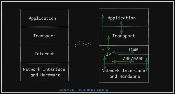
Network Layer Protocols
- Host-to-Host Communication: Enables communication between devices across different networks.
- Logical Addressing: Assigns unique addresses that identify both the device and its network.
- Routing: Forwards packets toward the destination based on logical addressing, typically using routers.
- Fragmentation: Splits large packets into smaller fragments to accommodate networks with lower data-carrying capacities, ensuring reliable transmission.
Takeaway
- Ethernet Frame Structure: Ethernet frames encapsulate data for transmission, including essential fields like source and destination MAC addresses, type, data, and error-checking (CRC).
- CSMA/CD: Helps devices detect collisions on the network and manage retransmissions, maintaining data integrity in half-duplex Ethernet environments.
- Ethernet Operations: Ethernet governs how data moves across a LAN — handling access control, error detection, and efficient delivery of frames between devices.
- Network Layer Protocols:
- Handle logical addressing to uniquely identify devices and their networks.
- Manage routing to forward packets to the correct destination via routers.
- Perform fragmentation to split large packets into smaller pieces when crossing networks with smaller maximum transmission units (MTUs).